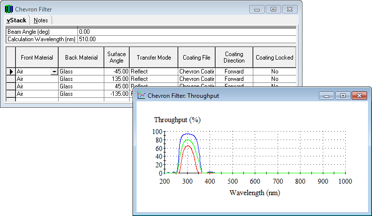
The light is assumed to consist of a ray that is traced through the system, being either reflected or transmitted by the various surfaces than can be coated and tilted at any angle in the plane of the instrument. Because there are multiple surfaces and many changes in direction of the ray that is sometimes reflected and sometimes transmitted, the term throughput in vStack replaces the more usual reflectance or transmittance. Throughput calculation follows one beam through the system. The user simply specifies the order of the surfaces, defines the various angles of the surface normals, applies any necessary coating, and specifies reflectance or transmittance at each surface. vStack takes care of the calculation of all the angles of incidence through the system. An adjustable beam angle allows the beam direction to be varied without altering the vStack. Optical systems almost invariably contain some tilted surfaces, and, therefore, exhibit a polarization sensitivity. Hence the ellipsometric terms ψ and are calculated. ψ and are chosen because they do not depend on the absolute distances between the surfaces.
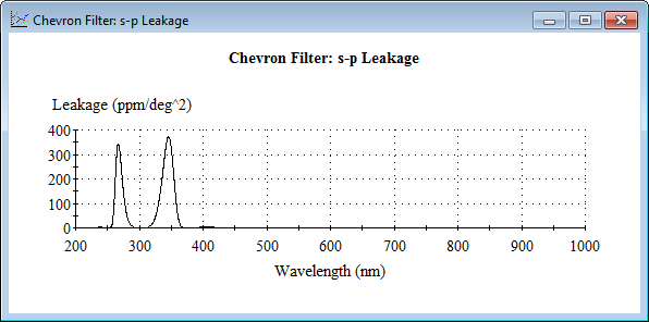
The geometry ensures that the local plane of incidence always coincides with the plane of the instrument, implying no mixing of p- and s-polarized light. If the beam direction were tilted out of the plane of the instrument, through a skew angle, this would no longer be true. Some light, originally s-polarized, would emerge finally from the system as p-polarized, and some p-polarized as s-polarized. We call this effect polarization leakage and to a second order it is proportional to the square of the skew angle. Thus we have a new performance parameter, polarization leakage coefficient that describes this effect. Coating design does affect the polarization leakage coefficient, although not to the extent possible with, say, reflectance or transmittance, and so it a refinable parameter.

The straightforward vStack calculation involves just one beam. Many systems, however, include single, or even multiple, beam splitters. In order that the properties of such systems may be optimized, a process called corefinement has been introduced. Here a number of vStacks can be refined simultaneously with a single common merit function. These various vStacks may be simply versions of a single system, each with a different beam path, or they can even be completely separate systems.
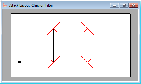
It can be imagined that setting up a complex vStack, where surfaces are tilted at different angles, and the beam is reflected at some, and transmitted by others, might be a demanding task. It could be fairly easy to mistakenly arrange a surface so that the beam might strike it on the incorrect side or miss it altogether. To make the vStack specification much more straightforward, a graphical layout tool is provided. This automatically sketches the vStack layout showing the path of the beam through the system and the orientations of the various surfaces. Use of this tool makes the construction of a vStack very easy.

All products and services may be ordered directly from Thin Film Center or from any of our agents. For your convenience we accept payment by American Express, Mastercard and Visa. Please contact us, or our agents for pricing information.

2745 E Via Rotunda, Tucson, AZ
85716-5227, USA
Telephone: +1 520 322 6171
Email: info@thinfilmcenter.com
